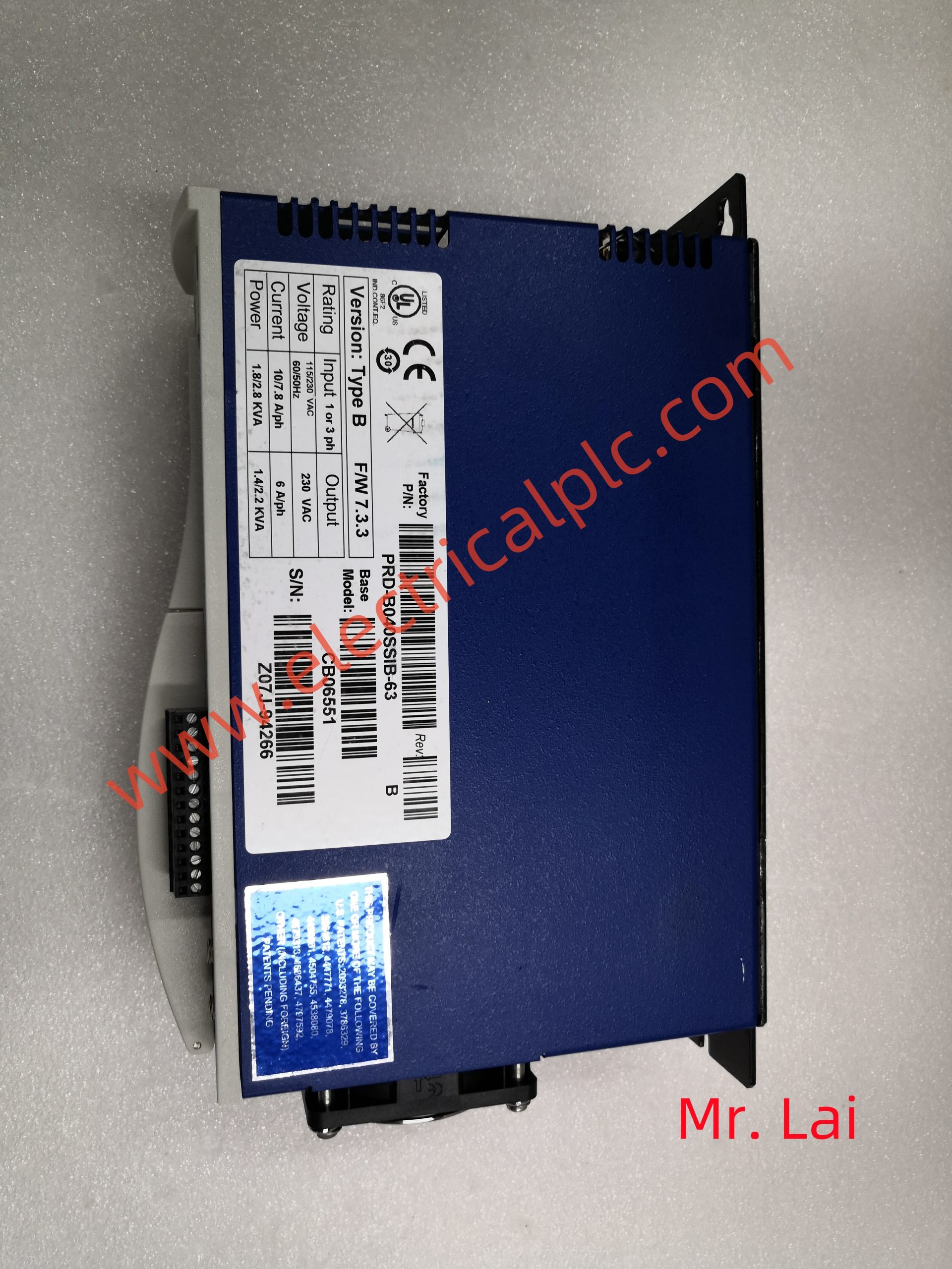
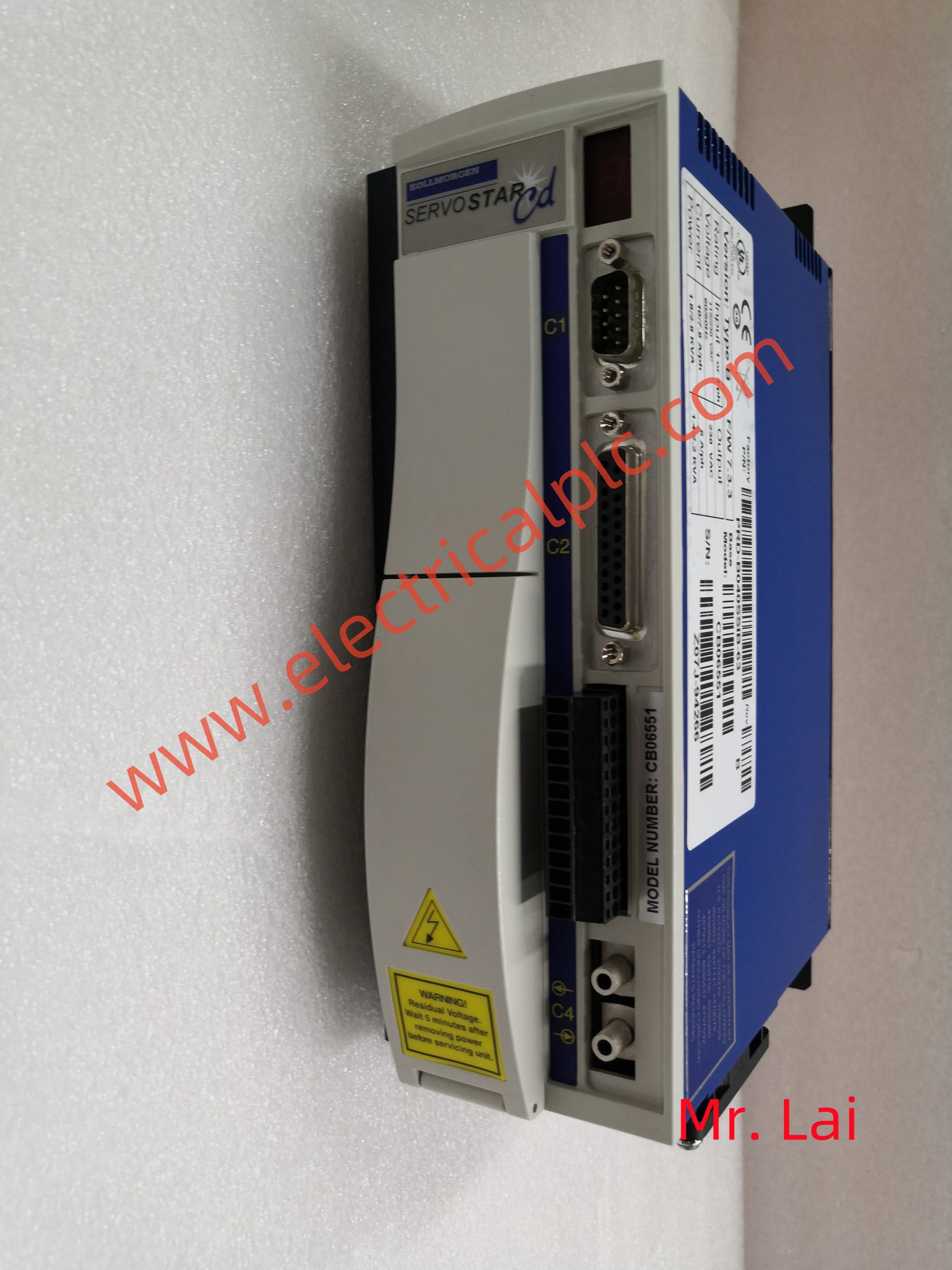
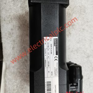
CB06551 Colmorgen servo drive
CB06551 Colmorgen servo drive
 1. The control memory (contmlMemory) is used to store the microprograms corresponding to each machine instruction. The decoder is used to form the entry address of the microprogram corresponding to machine instructions. When the microinstructions of a microprogram corresponding to a machine instruction are retrieved one by one and sent to the microinstruction register, the micro operation commands are issued according to the predetermined design, thus completing the function of a machine instruction. This applies to every machine instruction.
2. The width of microinstructions directly determines the width of the microprogram controller. To simplify the control of memory, some measures can be taken to shorten the width of microinstructions. If the field decoding method is used for first level segmentation decoding. Obviously, the control fields of microinstructions will be greatly shortened., Some micro operation commands that need to be generated simultaneously cannot be arranged in the same field. To further shorten the control field, the field decoding can also be designed as two or more levels.
The executing component reflects the operation status to the control component through feedback lines, so that the control component can issue new micro commands based on the status of the executing component, which is also called “state testing”. Micro operations are fundamental operations in executing components. Due to the structural relationship of data pathways, micro operations can be divided into
There are two types: compatibility and repulsion. In one CPU cycle of a machine, a combination of micro commands that implement certain operational functions constitutes a micro instruction. The general microinstruction format consists of two parts: operation control and sequence control. The operation control part is used to issue control signals for managing and commanding the operation of the entire machine. The sequence control part is used to determine the address for generating the next microinstruction. In fact, the function of a machine instruction is implemented by a sequence of many microinstructions. This microinstruction sequence is usually called a microprogram. Since microprograms are composed of microinstructions, when executing the current microinstruction. It is necessary to indicate the address of the subsequent microinstruction so that the next microinstruction can be executed after the current microinstruction is completed.
LED
The LED controller is a chip that processes and controls the switches at various positions in the LED light circuit.
Low voltage LED product controller:
Low voltage LED products are generally designed with a voltage of 12V-36V, with 3-6 LEDs connected in series in each circuit. Resistors are used to reduce voltage and limit current, with a current of less than 20mA per circuit. An LED product consists of multiple LED circuits, with the advantages of low voltage, simple structure, and easy design; The disadvantage is that when the product scale is large, the current is high and a low-voltage switching power supply needs to be configured. Due to the limitations of the product, low voltage cannot be transmitted over long distances and is limited to products with small volumes, such as signage text, small patterns, etc. Based on this characteristic, the controller design specifications are as follows: for 12V, 75A/30V MOS power transistor control is selected, with an output current of 8A/channel; 24-36V is controlled by a 60A/50V MOS power transistor, with an output current of 5A per circuit. Users can select the number of channels for the controller based on the above specifications. For jump mode, they can choose the NE20 low-voltage series, and for gradient mode, they can choose the NE10 low-voltage series controller. Note that the LED must be connected to the common anode (+) pole, and the controller controls the cathode (-) pole. The controller does not include a low-voltage power supply
High voltage LED product controller:
The design voltage of high-voltage LED products is AC/DC 220V voltage, with 36-48 LEDs connected in series in each circuit. Each circuit has a current of less than 20mA, and there are two current limiting methods. One is resistor current limiting, which consumes a lot of power. It is recommended to use a 1/4W metal mold resistor connected in series with every 4 LEDs to evenly distribute heat dissipation. This connection method is stable and reliable; Another method is to limit the current by connecting resistors and capacitors in series
5. According to the structure of the rotor, it can be divided into cage type induction motors (formerly known as squirrel cage asynchronous motors) and wound rotor induction motors (formerly known as wound type asynchronous motors).
6. According to operating speed, it can be divided into high-speed motors, low-speed motors, constant speed motors, and speed regulating motors. Low speed motors are divided into gear reduction motors, electromagnetic reduction motors, torque motors, and claw pole synchronous motors.
Adjustable speed motors can be divided into stepped constant speed motors, continuously variable speed motors, stepped variable speed motors, and continuously variable speed motors. They can also be divided into electromagnetic speed motors, DC speed motors, PWM frequency conversion speed motors, and switched reluctance speed motors.
The rotor speed of an asynchronous motor is always slightly lower than the synchronous speed of the rotating magnetic field.
The rotor speed of a synchronous motor remains synchronous regardless of the load size.
The working principle of a DC generator is to convert the alternating electromotive force induced in the armature coil,
The direction of force acting on a conductor is determined by the left-hand rule. This pair of electromagnetic forces forms a torque acting on the armature, which is called electromagnetic torque in a rotating motor. The direction of the torque is counterclockwise, attempting to make the armature rotate counterclockwise. If this electromagnetic torque can overcome the resistance torque on the armature (such as the resistance torque caused by friction and other load torques), the armature can rotate counterclockwise.
DC motor is an electric motor that operates on DC working voltage and is widely used in recorders, video recorders, DVD players, electric shavers, hair dryers, electronic watches, toys, etc.
Electromagnetic Editing
An electromagnetic DC motor consists of stator magnetic poles, rotor (armature), commutator (commonly known as commutator), brushes, casing, bearings, etc,
The stator magnetic pole (main magnetic pole) of an electromagnetic DC motor is composed of an iron core and an excitation winding. According to the different excitation methods (formerly known as excitation), it can be divided into series excited DC motors, parallel excited DC motors, separately excited DC motors, and compound excited DC motors. Due to different excitation methods, the law of stator magnetic flux (generated by the excitation coil of the stator magnetic pole after being energized) is also different.
1. The control memory (contmlMemory) is used to store the microprograms corresponding to each machine instruction. The decoder is used to form the entry address of the microprogram corresponding to machine instructions. When the microinstructions of a microprogram corresponding to a machine instruction are retrieved one by one and sent to the microinstruction register, the micro operation commands are issued according to the predetermined design, thus completing the function of a machine instruction. This applies to every machine instruction.
2. The width of microinstructions directly determines the width of the microprogram controller. To simplify the control of memory, some measures can be taken to shorten the width of microinstructions. If the field decoding method is used for first level segmentation decoding. Obviously, the control fields of microinstructions will be greatly shortened., Some micro operation commands that need to be generated simultaneously cannot be arranged in the same field. To further shorten the control field, the field decoding can also be designed as two or more levels.
Reviews
There are no reviews yet.