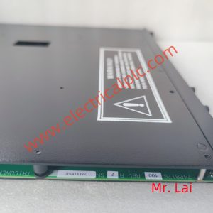
4210 IO module Triconex
4210 IO module Triconex
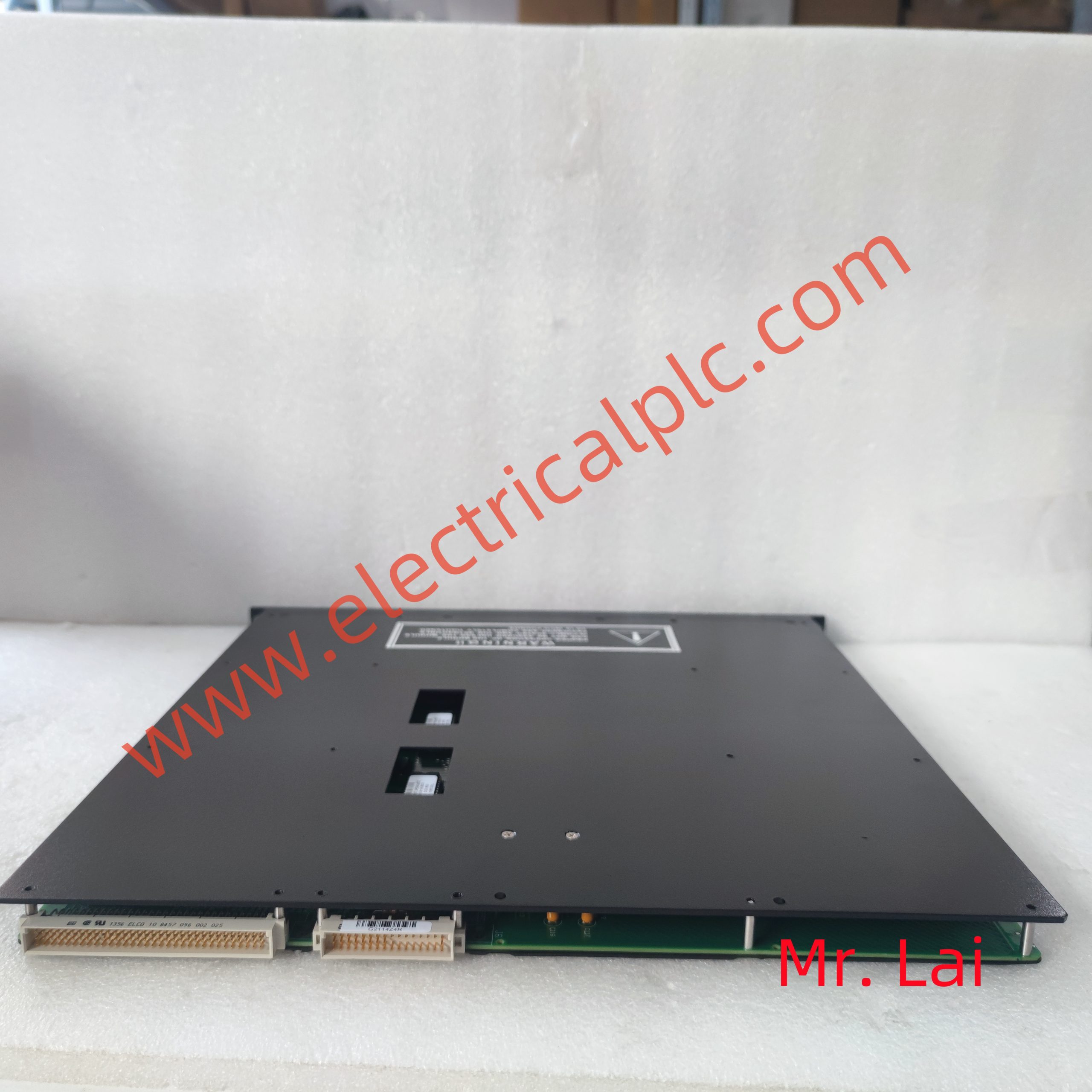
PLCs are mainly composed of CPU modules, input modules, output modules, and programmers (see Figure 1). Some PLCs can also be equipped with special functional modules to complete certain special tasks.
1. CPU module
The CPU module is mainly composed of a microprocessor (CPU chip) and a memory. In PLC control systems, the factory CPU module is equivalent to the human brain, constantly collecting input signals, executing user programs, and refreshing system outputs; Memory is used to store programs and data.
2. I/O module
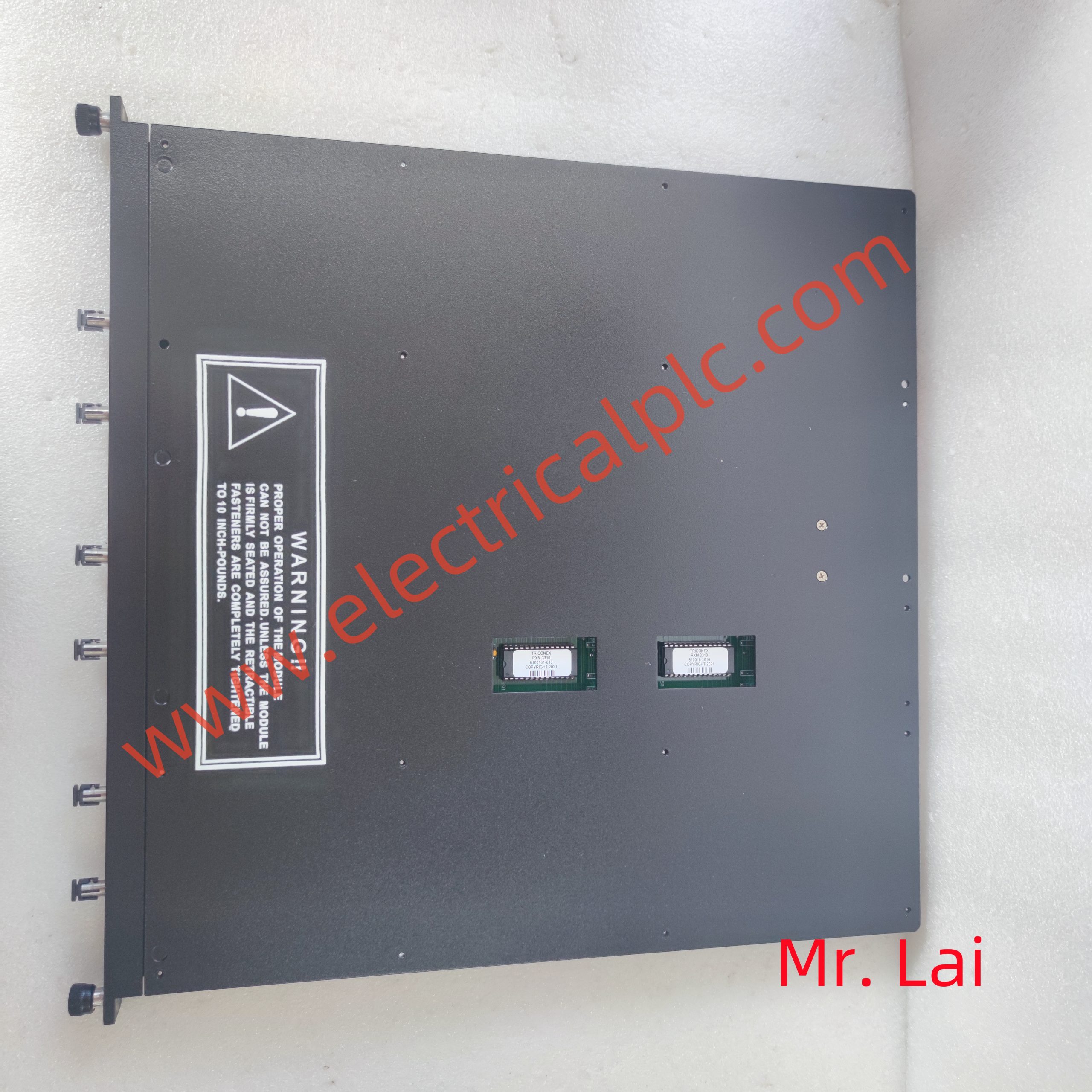
The input module and output module, abbreviated as I/O module, are the eyes, ears, hands, and feet of the system, serving as a bridge between external field devices and CPU modules.
The input module is used to receive and collect input signals, while the switch input module is used to receive slave buttons; Select switch, digital dial switch, limit switch, proximity switch, photoelectric switch, pressure relay and other switch input signals; The analog input module is used to receive continuously changing analog current and voltage signals provided by potentiometers, speed generators, and various transmitters.
The switch output module is used to control output devices such as contactors, solenoid valves, electromagnets, indicator lights, digital display devices, and alarm devices, while the analog output module is used to control execution devices such as regulating valves and frequency converters.
The working voltage of CPU modules is generally 5V, while the input/output signal voltage of PLCs is generally higher, such as DC 24V and AC 220V. The peak voltage and interference noise introduced from the outside may damage the components in the CPU module or cause the PLC to malfunction. In the I/O module, optocouplers, phototransistors, small relays, and other devices are used to isolate the internal and external I/O circuits of the PLC. In addition to transmitting signals, the I/O module also has the function of level conversion and isolation.
3. Programmer
Programmers are used to generate user programs and to edit, check, modify, and monitor the execution of user programs. Handheld programmers cannot directly input and edit ladder diagrams, they can only input and edit instruction table programs, so they are also called instruction programmers. It is small in size and inexpensive, usually used for programming small PLCs or for on-site debugging and maintenance.
Programming software can be used to directly generate and edit ladder diagrams, instruction lists, functional block diagrams, and sequential functional diagram programs on the computer screen, and can achieve mutual conversion between different programming languages. The program can be compiled and downloaded to the PLC, or the program in the PLC can be uploaded to the computer. The program can be saved or printed, and remote programming and transmission can also be achieved through the network.
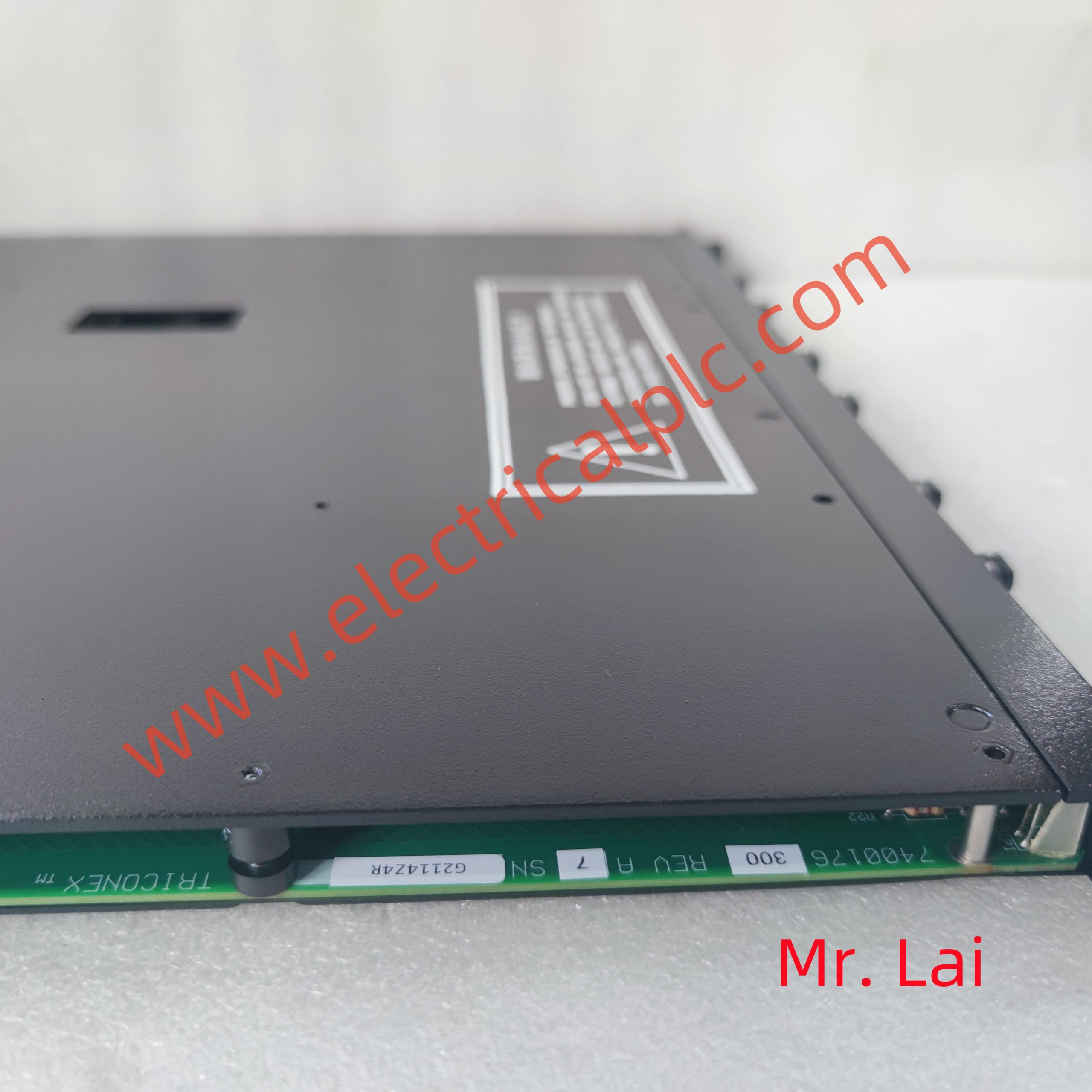 4. Power supply
PLCs generally use 220V AC power or 24V DC power. The internal switch power supply provides DC 5V, ± 12V, 24V and other DC power sources for each module. Small PLCs can generally provide 24V DC power supply for input circuits and external electronic sensors (such as proximity switches), and the DC power supply for driving PLC loads is usually provided by the user.
1. The programming method is simple and easy to learn
Ladder diagram is the most commonly used programming language for PLCs, with circuit symbols and expressions similar to relay circuit schematics. The ladder diagram language is visual, easy to learn, and understandable. Electrical technicians familiar with relay circuit diagrams can familiarize themselves with ladder diagram language in just a few days and use it to develop user programs.
Ladder diagram language is actually a high-level language aimed at users. When PLC executes ladder diagram programs, it “translates” them into assembly language before execution.
2. Strong functionality and high cost performance ratio
A small PLC contains hundreds or thousands of programming elements that can be used by users, with strong functionality and the ability to achieve very complex control functions. Compared with relay systems with the same functionality, it has a high cost performance ratio. PLC can achieve decentralized control and centralized management through communication networking.
3. The hardware is fully equipped, making it easy for users to use and highly adaptable
PLC products have been standardized, serialized, and modularized, equipped with a complete range of hardware devices for users to choose from. Users can flexibly and conveniently configure the system to form systems with different functions and scales. The installation and wiring of PLC are also very convenient, usually connected to external wiring through terminal blocks. PLC with load capacity can directly drive general solenoid valves and small and medium-sized AC contactors.
After the hardware configuration is determined, it can be easily and quickly adapted to changes in process conditions by modifying the user program.
4. High reliability and strong anti-interference ability
Traditional relay control systems use a large number of intermediate relays and time relays. Due to poor contact of the contacts, malfunctions are prone to occur. PLC replaces a large number of intermediate relays and time relays with software, leaving only a small number of hardware components related to input and output. Wiring can be reduced to one tenth to one percent of the relay control system, greatly reducing faults caused by poor contact.
PLC uses a series of hardware and software anti-interference measures, with strong anti-interference ability and an average time between failures of tens of thousands of hours or more. It can be directly used in industrial production sites with strong interference, and is widely recognized as one of the reliable industrial control equipment by PLC large users.
5. The design, installation, and debugging of the system require less work
PLC replaces a large number of intermediate relays, time relays, counters and other components in relay control systems with software functions, greatly reducing the workload of design, installation and wiring of control cabinets.
The ladder diagram program of PLC can be designed using sequential control design method. This programming method is very regular and easy to master. For complex control systems, if the correct design methods are mastered, designing ladder diagrams takes much less time than designing relay system circuit diagrams.
The user program of PLC can be simulated and debugged in the laboratory. The input signal is simulated using a small switch, and the output signal status can be observed through the PLC’s light-emitting diode. After completing the installation and wiring of the system, problems discovered during on-site debugging can generally be solved by modifying the program, and the debugging time of the system is much shorter than that of the relay system.
6. Small maintenance workload and convenient maintenance
The fault rate of PLC is very low, and it has complete self diagnosis and display functions. When PLC or external input devices and actuators fail, the cause of the fault can be easily identified based on the information provided by the LED or programmer on the PLC, and the fault can be quickly eliminated by replacing the module.
7. Small size, low energy consumption
For complex control systems, the use of PLC can reduce a large number of intermediate relays and time relays. The size of a small PIC is only equivalent to the size of a few relays, so the volume of the switchgear can be reduced to 1/2 to 1/10 of its original size.
The wiring of PLC control system is much less than that of relay control system, so it can save a lot of wiring and accessories, reduce a lot of installation and wiring time, and with the reduction of switchgear volume, it can save a lot of costs.

Reviews
There are no reviews yet.